Master the editor
Every tool, shortcut and feature. Open the editor and try each step as you read.
5-Minute Quick Start Guide
Get up to speed in 5 simple steps. Open the editor in another tab to follow along live.
1. Draw a shape
Press R for Rectangle or E for Ellipse and drag on the canvas, or press P for the Bézier Pen and click to place anchor points.
2. Edit path nodes
Press A for Direct Selection. Click any anchor point or control handle to bend curves and reshape contours precisely.
3. Apply color & style
Select your shape and use the Inspector to set fills, strokes, or linear/radial gradients. Sample any canvas color with the pipette.
4. Add CAD dimensions
Press U for the Dimension tool and click the two things you want to measure between. Edit the value and the geometry solves to match.
5. Export clean SVG
Click Export… in the top bar and download standards-valid SVG. Exporting needs a free account; SVG export is never watermarked.
Getting started
Anchorsmith opens on an anonymous scratchpad, with no account needed. Draw on the central canvas; your work lives inside an artboard that defines the exported bounds. The tool rail runs down the left, and the panels on the right hold the Inspector (fill, stroke, and appearance), Layers, Artboards, and Constraints.
Everything autosaves to the scratchpad as you work. Sign in when you want to save documents to the cloud or export your work. Press ? at any time for the live keyboard-shortcuts dialog.
Interface & workspace controls
The editor has four regions: the top bar for document actions, the tool rail down the left, the panel column on the right, and the status bar along the bottom with zoom, snapping, and the workspace toggles. Everything between them is canvas.
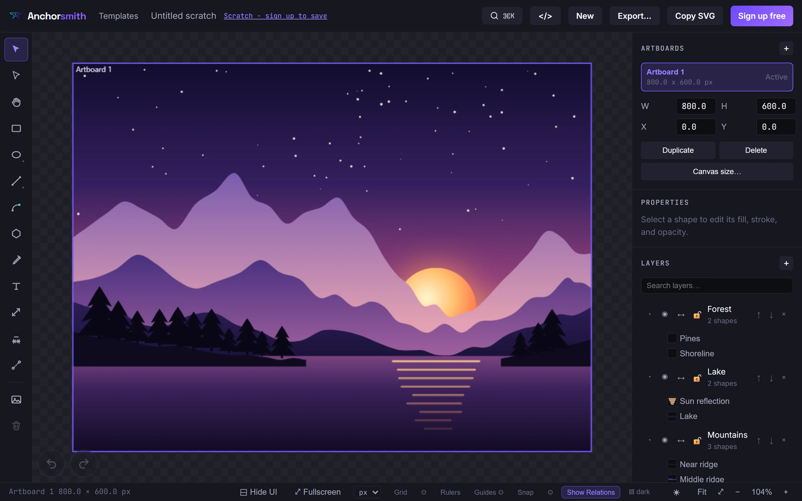
On a phone or a narrow window the layout changes rather than shrinks. The rail and the panel column stop taking space from the canvas and become overlays that slide in over it, hidden until you ask for them — otherwise the two together would leave a 320px-wide screen with almost no drawing surface. A round button in each top corner brings its side back, and swiping in from that edge does the same thing faster. Only one side opens at a time, deliberately: on the narrowest screens two open panels would cover the drawing entirely. Swipe a panel away, or tap its button again, to dismiss it.
Two controls sit on the canvas itself at those widths. Undo and redo are the pair at the bottom-left — on touch they are the only route, since there is no Ctrl key. The pan button at the bottom-centre switches to one-finger panning; two-finger panning and pinch-zoom work at any time without it.
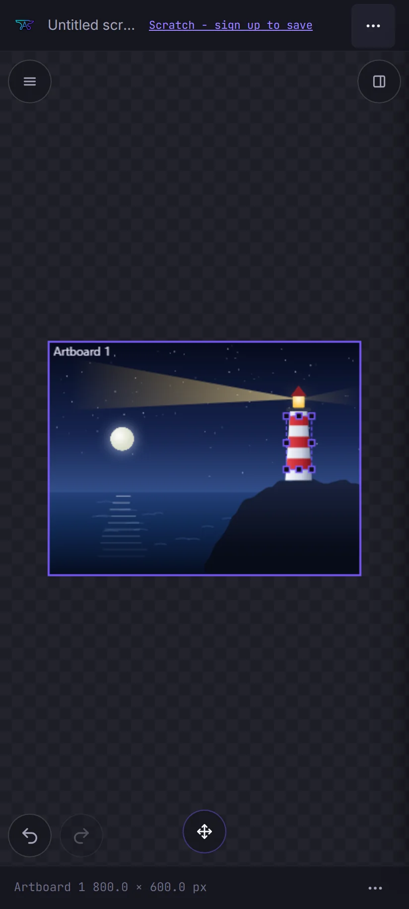
Hide UI (Tab, or the button in the status bar) clears the chrome away for a clean view of the drawing. What it hides depends on your screen, and the difference is deliberate: on a desktop it also hides the undo and redo buttons, because Ctrl+Z still works there; on a touch screen it leaves them, because hiding them would leave you with no undo at all. A single button stays on screen to bring the interface back, so this is never a one-way door.
Fullscreen is separate from Hide UI — it removes the browser's interface where Hide UI removes ours, and the two combine freely. You will only see the control if your browser supports fullscreen for ordinary elements; on iPhone Safari it is absent rather than present-and-broken, because iOS allows fullscreen for video only. While fullscreen is active an exit button sits at the bottom-right, since the browser's own way out is gone too.
Tools
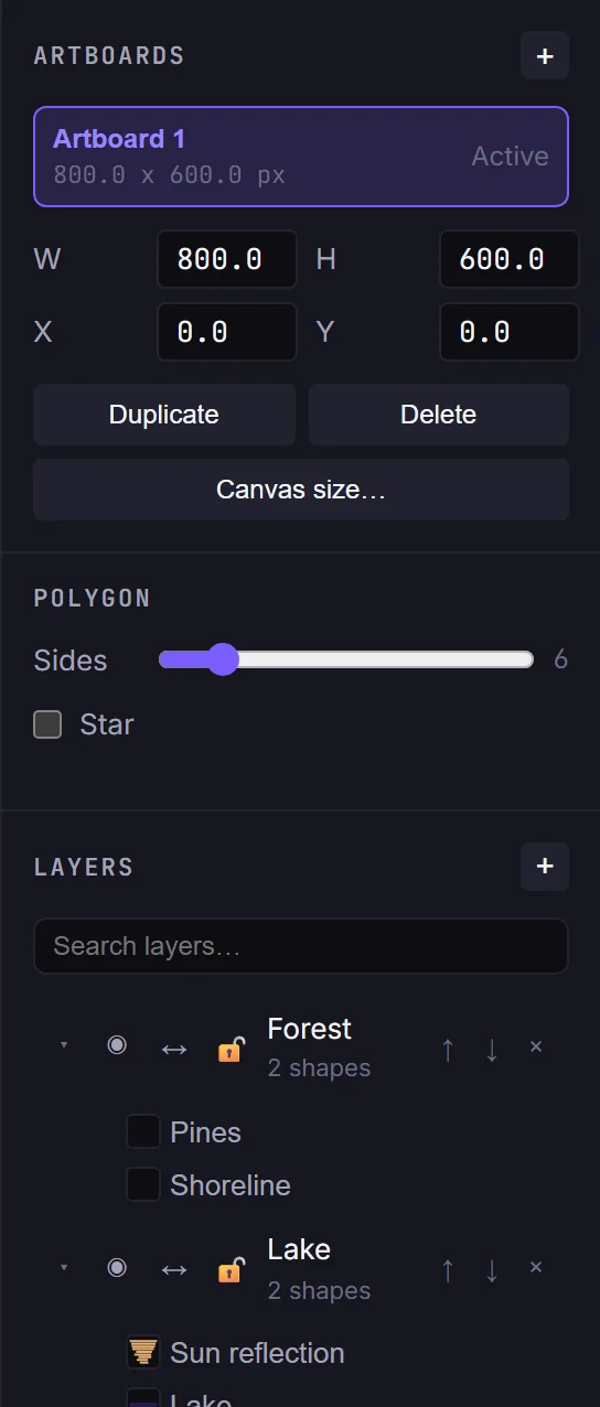
Pick a tool from the rail or press its shortcut key. Twelve tools cover drawing, editing, and measuring.

Selection
VSelect, move, and scale whole shapes, text, images, and dimensions.
- Click a shape to select it; drag its body to move it.
- Drag one of the eight bounding-box handles (corners + edge midpoints) to scale.
- Shift-click to add or remove a shape from a multi-selection.
- Hold Shift while scaling to keep the aspect ratio. Images lock aspect on corner handles automatically.
- Drag on empty canvas for a marquee; it selects shapes, text and images fully enclosed by the rectangle.
- Delete or Backspace removes the selection; Escape clears it.
- Right-click for cut / copy / paste / duplicate / delete, group / ungroup, arrange (front, forward, backward, back), and reverse path direction.
- Scaling a strict circle or arc non-uniformly prompts to convert it to an editable path first.
Direct Selection
AEdit a path's individual anchors, control handles, and segments.
- Click an anchor or handle to select it, then drag; the point snaps directly under the cursor.
- Drag a segment to bend it: a straight line becomes a curve, an existing curve moves its nearest handle.
- Double-click a segment to insert a new anchor there.
- Shift- or Ctrl-click to add nodes to the selection; drag empty canvas for a node marquee.
- Alt-drag an existing handle to break its symmetry; Alt-drag an anchor that has no handles to pull a new pair out of it.
- With an anchor selected, press M / A / C / S to set its handle type: Mirror, Asymmetric, Corner, or Single.
- Arrow keys nudge selected nodes by 1 unit (10 with Shift); Delete removes nodes; Escape cancels a drag.
Selecting multiple nodes
- Click a node to select just it.
- Ctrl+click (Cmd+click on Mac) toggles individual nodes: click each node to add it to the selection, and Ctrl/Cmd+click a selected node to remove it. No drag or pre-selection needed.
- Shift+click extends the selection along the path by node type (corner, smooth/mirrored, asymmetric, single-handle), keyed off the type of your first-selected node. Shift+click an adjacent node to select the run of consecutive same-type nodes continuing in that direction (until the type changes or the path ends); shift+click a farther node to select the same-type nodes in the span between your current node and the one you click. Shift+clicking a node on a different path just toggles it, like Ctrl+click.
- Dragging any selected node moves all selected nodes together, as do the arrow keys (nudge) and Delete.
- You can also marquee-drag on empty canvas to box-select nodes (hold Shift or Ctrl to add to the selection).
Pen
PDraw paths one anchor at a time.
- Click to place a corner point; click-drag to place a smooth Bézier point (mirrored handles).
- Hold Alt while dragging to make the handle asymmetric instead of mirrored.
- Click the start point to close the path; press Enter to finish it open.
- Backspace removes the last point; Escape cancels the whole in-progress path.
- While dragging a handle, M / A / S / C set the point's handle type.
Rectangle
RDrag to draw a rectangle.
- Hold Shift to constrain to a square.
- Corners snap to the grid when snapping is on; Escape cancels the drag.
Ellipse
EDrag to draw an ellipse.
- Hold Shift to constrain to a true parametric circle (a strict curve; see “Strict vs free curves”).
- Snaps to the grid when snapping is on; Escape cancels.
Line
LDrag to draw a straight line.
- Hold Shift to snap the angle to 45° increments.
- Lines default to a stroke with no fill; Escape cancels.
Polygon
GDrag from the centre outward to draw a polygon or star.
- Options bar: sides (3 to 24), a Star toggle, and, in star mode, an inner-radius percentage.
- Hold Shift to snap the angle to 45° increments.
Text
TAdd and edit point text.
- Click empty canvas to add text and start typing; click existing text to edit it.
- Enter commits, Escape cancels; empty text is discarded.
- Before cutting, engraving or plotting, convert text to outlines: Convert to outlines in the Text inspector, or Convert Text to Outlines in the command palette. Inter and Mono text can be outlined; switch other fonts first, and turn off bold and italic.
Eyedropper
ICopy a shape's appearance into the current draw style.
- Click a shape to pick its fill and stroke (enabled state, color, and stroke width) into the draw style used for new shapes.
Measure
MRead distances and angles without changing the artwork.
- Click two points to see the distance plus DX, DY, and angle in the document unit.
- Hover a segment to read its length; Escape resets the measurement.
Dimension
UPlace CAD dimension annotations; the type is inferred from what you pick.
- Click a circle for a radius; a line then empty space for a length; a line then a second line for an angle; two points for a fixed distance.
- Snaps to the midpoint of existing geometry as you place: a straight segment reports Segment midpoint, a curve reports Curve midpoint. The snap label confirms you've caught the middle, not a nearby anchor.
- Dimensions are non-exporting annotations. Right-click or Escape cancels a placement.
Constraints
KAdd geometric constraints to selected points or line segments.
- With geometry selected, press a key: C coincident, H horizontal, V vertical, P parallel, O perpendicular, D fixed-distance, E equal-length, A angle, L collinear.
- A constraint can reference a segment or curve midpoint, not only an anchor: snap to the midpoint and the relation is built from that point.
- The solver applies the constraint across the whole sketch, or rejects a selection that can't form it or would over-constrain the sketch.
Node handles
A handle is the lever that decides how a curve leaves an anchor: its direction sets which way the curve heads, its length sets how far the curve keeps going before it turns. Pick Direct Selection (A) and click an anchor, and the Inspector grows a Handles row. Every figure below is a real screenshot of that editor with the anchor selected, so the dots and leashes are the ones you will actually see.
The four handle types
The Handles row sets what the two sides of an anchor are allowed to do to each other. With an anchor selected you can also press M, A, S or C. All four figures below are the same anchor on the same path, so only the type differs; in the Mirror and Asymmetric shots the right-hand handle has been dragged by the same amount, which is the only way those two ever look different.
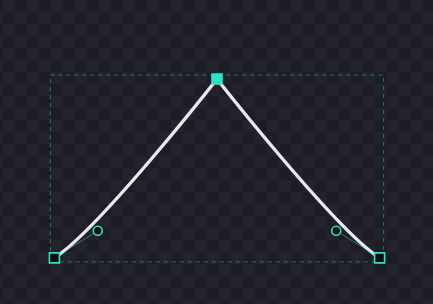
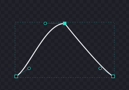
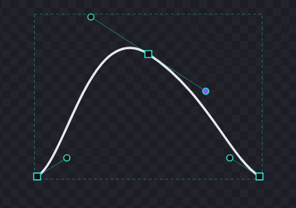
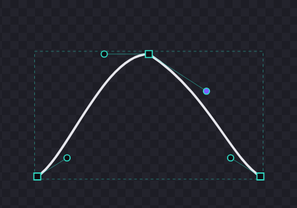
- Corner — for a hard crease: a corner of a bracket, the tip of a star, anywhere the outline is meant to turn a sharp angle rather than round off.
- Single — for a curve that straightens on one side, like an arc running into a straight edge. Only one side keeps a handle.
- Mirror — the default for smooth work. Both handles stay equal and opposite, so the curve flows through the anchor with no visible join, and adjusting one side adjusts both.
- Asymmetric — smooth-but-uneven: the two sides move independently, so you can make the curve tight on one side of an anchor and loose on the other.
Adding and removing a handle on one side
Each side of an anchor can carry a handle on its own. With an anchor selected the Inspector offers + In Handle, + Out Handle, - In Handle and - Out Handle. In is the side facing the previous anchor, out the side facing the next one.
- All four are always present. One you cannot use right now is greyed out rather than hidden, and hovering it tells you why — that side already has a handle, it has none to remove, or the node has no segment on that side at all. Nothing disappears, so you never have to wonder whether you have hit a rule or a bug.
- Some nodes genuinely have only one side: the two ends of an openpath, since nothing precedes the first anchor and nothing follows the last. The missing side's buttons stay on screen, greyed, and say so when you hover them.
- Select a handle itself rather than its anchor and the Inspector shows a Handle row with Retract, which pulls that one handle back into its anchor.
Shared handles: Separate and Link
Some curves are quadratic: a single control is shared by the anchors at both ends, so it shows as one dot with a leash running to each of them. Moving it moves both sides at once. Separate gives each anchor its own control, and Link In or Link Out merges them back into one.
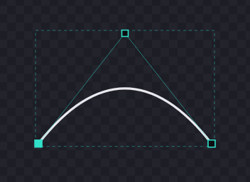
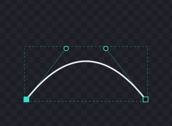
- Those two pictures are the same curve. Separating changes nothing about the shape, only about what you can grab — which is exactly why the handles, not the outline, are the difference.
- Separate and then link straight back without touching anything and you get the original curve returned to you unchanged.
- Linking after you have moved the two controls apart is the one case that alters the shape: two controls have to become one, so the curve shifts to fit the single shared control. Your history records that step as Link Handles (adjusts curve) for exactly that reason.
Alt-drag does two different things
- Alt-drag an existing handle to break its symmetry: the anchor stops being Mirror and that side moves on its own.
- Alt-drag an anchor that has no handles — a corner — to pull a fresh pair of handles out of it and start curving the path there.
They are easy to confuse because it is the same key and the same gesture. What decides it is what sits under the cursor when you start: a handle, or a bare anchor.
When the editor asks first
Two kinds of geometry will not be reshaped silently, because in both cases curving the path would throw away something you deliberately set up.
- Editing the nodes of a strict circle or arc raises Disable strict mode? — its shape is driven by its centre and radius, not by anchors. Choose Disable strict mode to convert it to an editable path, or Cancel to leave it exact. You can convert it back later; see Strict vs free curves.
- Adding a handle to a segment held straight by a relation raises Remove line constraint?, naming the constraints involved. Curving that segment would break them, so pick Remove constraint & add handle to curve it anyway or Keep constraint to leave the segment straight.
Strict (parametric) vs free curves
Some contours are strict: stored as exact parametric geometry (a circle's centre and radius, or an arc's centre, radius, and angles) instead of editable Bézier anchors. Only circles and arcs can be strict; everything else, including a non-circular ellipse, is a free editable path. The anchors you see on a strict curve are a derived cache; the parameters are the source of truth, so the geometry stays mathematically exact.
Creating them
- Hold Shift with the Ellipse tool (E) to draw a true parametric circle.
- Tracing an image recognises near-perfect circles and emits them as strict circles.
Working with a strict curve
- Its handles render greyed to show they're locked. You can still move it, scale it uniformly, and flip it, all of which keep it strict.
- You can't drag its anchors or handles, or scale it non-uniformly: that would deform the exact geometry, so instead you're prompted to convert it to a path first.
- A strict circle or arc shows a radius / diameter readout, and the Dimension tool (U) can add a radius dimension that drives the radius directly: edit the value and the circle resizes.
Converting
Right-click a contour with the Direct Selection tool (A):
- Convert to Path turns a strict curve into freely-editable anchors, and you trade parametric exactness for full node editing.
- Convert to Circle / Convert to Arc re-fits a free contour that is actually a circle or arc back to exact parametric geometry.
Keyboard shortcuts
Tool keys are listed with each tool above. On macOS, use ⌘ where Ctrl is shown. Press ? in the editor for the always-current list.
Edit
View & help
Color, fills & strokes
The color picker
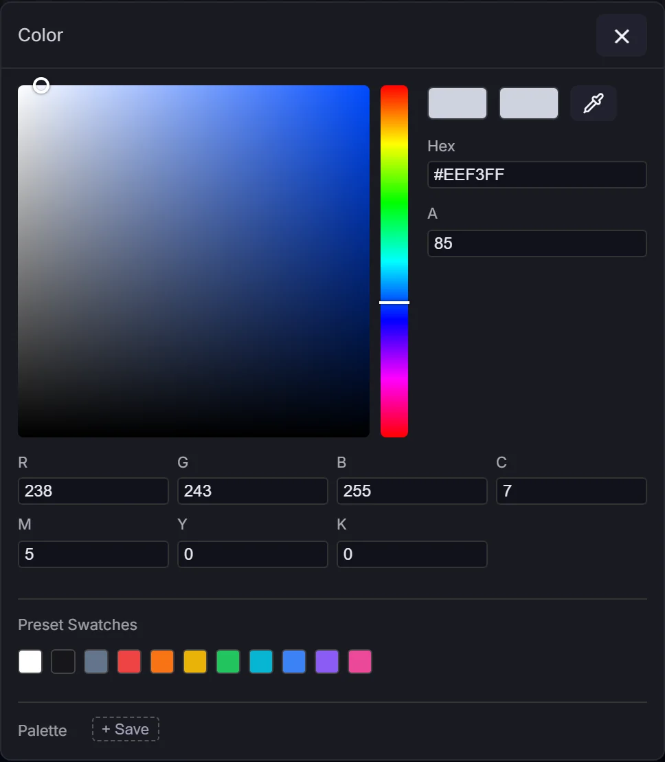
Every color swatch (fill, stroke, gradient stops, text, and guides) opens the same picker. Set color with the saturation/value square and the hue bar, or type it as Hex, RGB, CMYK, or an Alpha percentage. A New-vs-Current pair shows your change against the color you started with. The dialog is draggable by its title bar and stays within the window.
The eyedropper
The pipette in the picker is always available and adapts to your browser:
- Chrome / Edge: picks a color from anywhere on screen, including other apps (native EyeDropper).
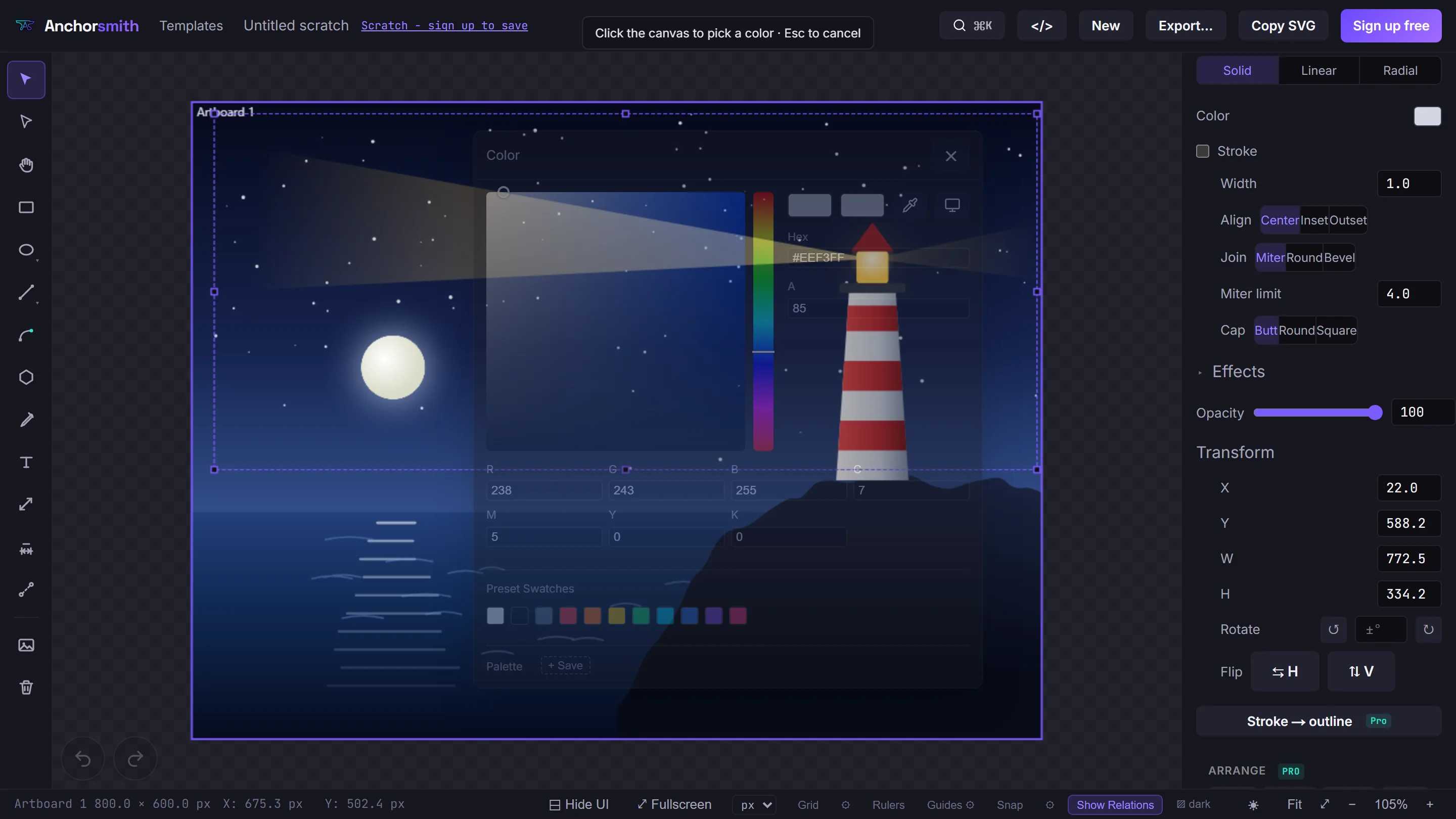
- Firefox / Safari:picks a color from your own canvas, with no permission needed. While it's armed the cursor becomes a crosshair; click the canvas to sample, or press Escape to cancel.
- Pick from another app: on Firefox / Safari a second button uses screen sharing to grab a single frame you can click to sample a color from any other window.
Gradients
Switch a fill or stroke between Solid, Linear, and Radial (a fill also offers Pattern, below). Click the gradient bar to add a stop, drag stops to reposition them, and edit each stop's color and offset (a gradient always keeps at least two stops). Linear gradients expose an angle; radial gradients a radius.
Gradient groups
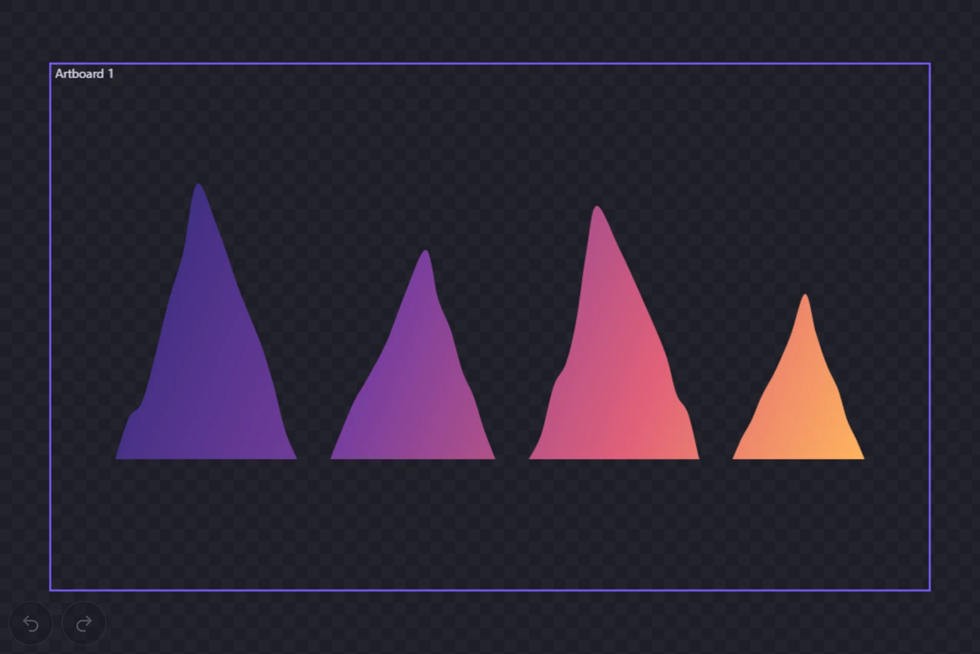
Group several shapes (select them and press Ctrl+G), then give the group a shared fill: one linear or radial gradient that spans the whole group's bounds, so the members read as a single continuous fill instead of each shape carrying its own gradient. With a group member selected, find the Inspector's Group Gradient Override section and use the Type control to choose Linear or Radial (or Clear to remove it), and set the Targetrow to apply the shared gradient to the group's fill or stroke. On export, every member references the single shared gradient. A per-shape gradient fills each shape individually; a shared group fill keeps the whole group aligned to one continuous gradient.
Pattern fills
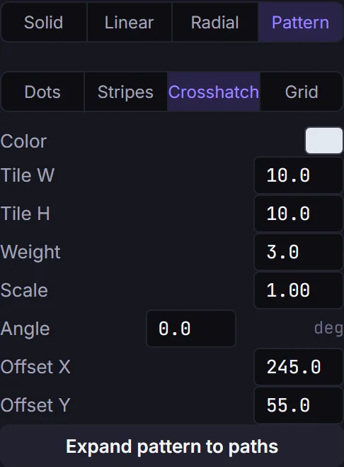
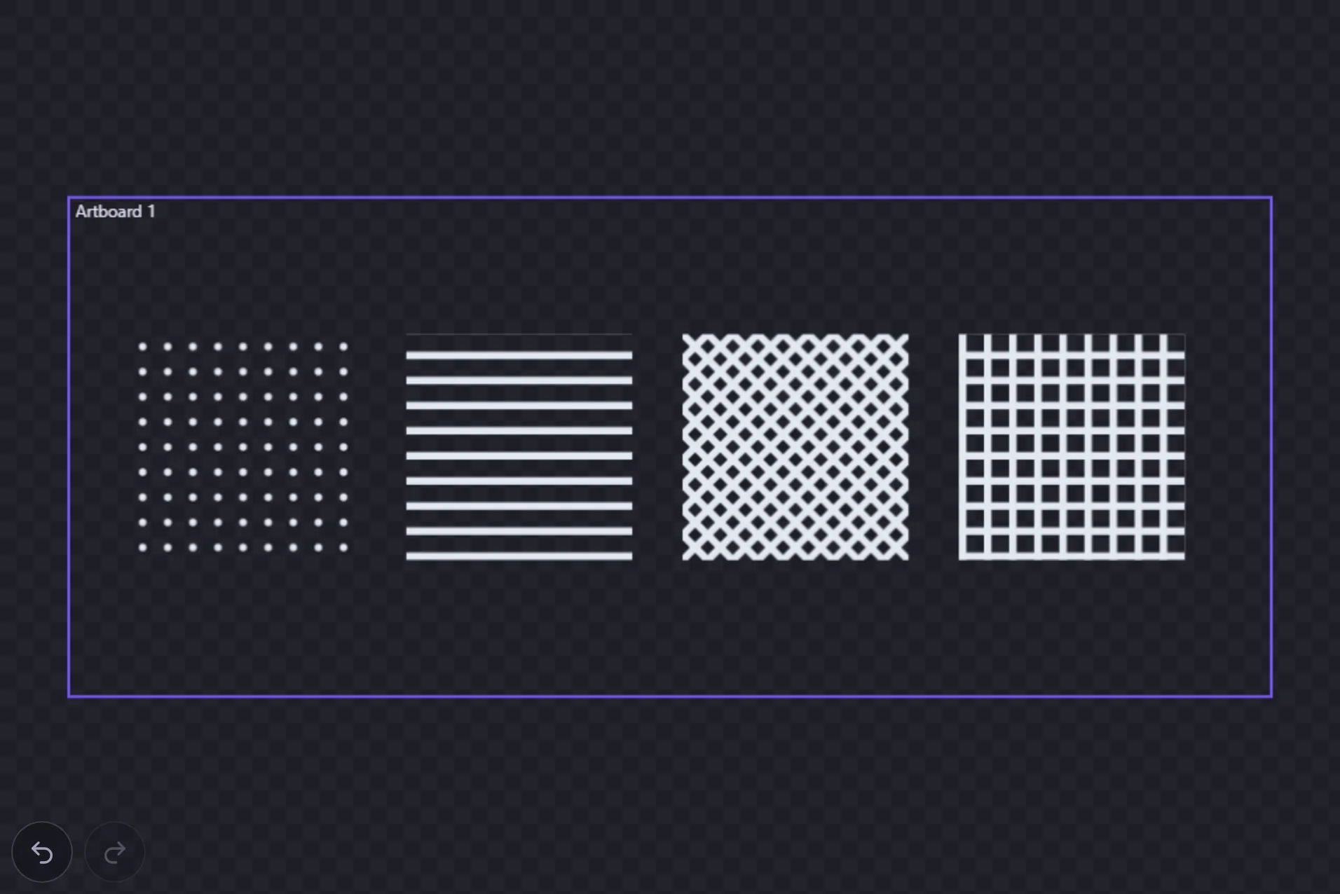
Select a shape and set its fill type to Pattern, then pick a preset: Dots, Stripes, Crosshatch or Grid. Underneath, set the pattern's Color, line Weight, Scale, Angle (counter-clockwise, in degrees) and Offset. Patterns are for fills only; a stroke stays Solid, Linear or Radial.
Expand pattern to paths
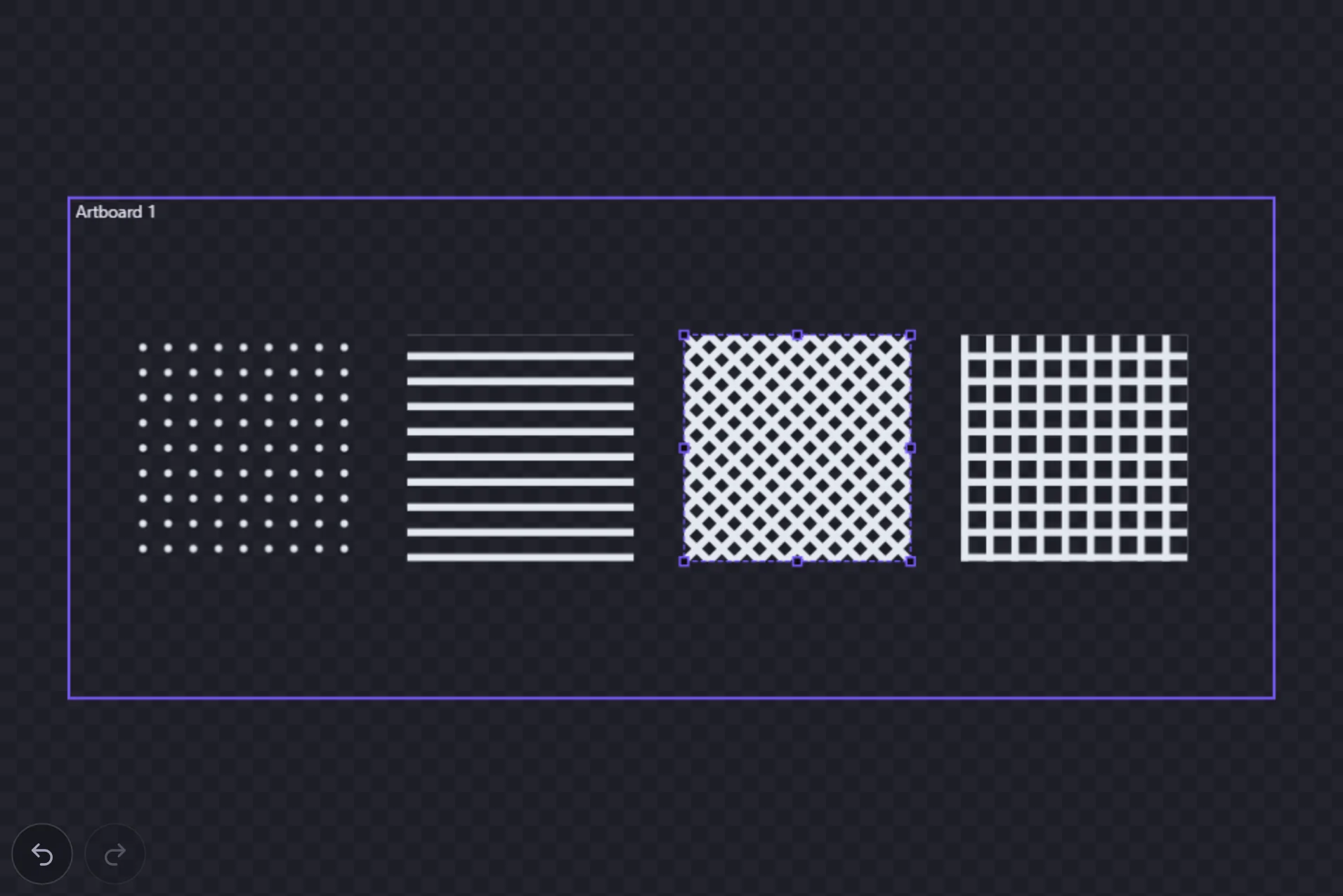
Cutters and plotters ignore pattern fills. Before you send a patterned shape to one, press Expand pattern to paths under the pattern controls: the pattern is written as ordinary paths, clipped to the shape, in one undo step. If the pattern would need more than 20,000 tiles the button says so. Raise the scale and try again.
Stroke join, cap & miter
The Inspector's stroke controls set the line Join (miter, round, bevel) and Cap (butt, round, square); changing them also updates the default for new shapes. The miter limit appears only for miter joins (currently applied to the selected shape).
Repeat, divide & outlines
Repeat: grids, rings and mirrors
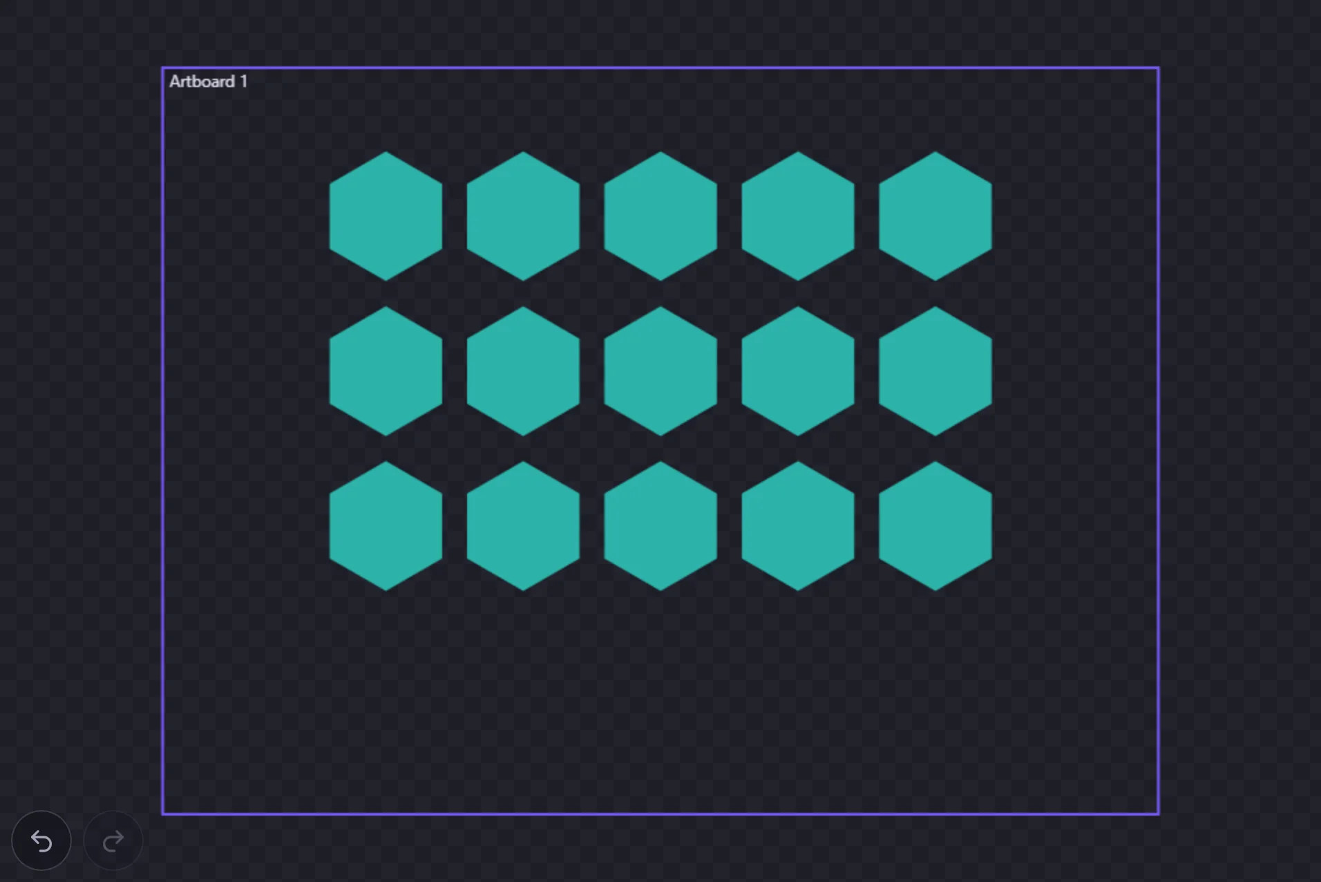
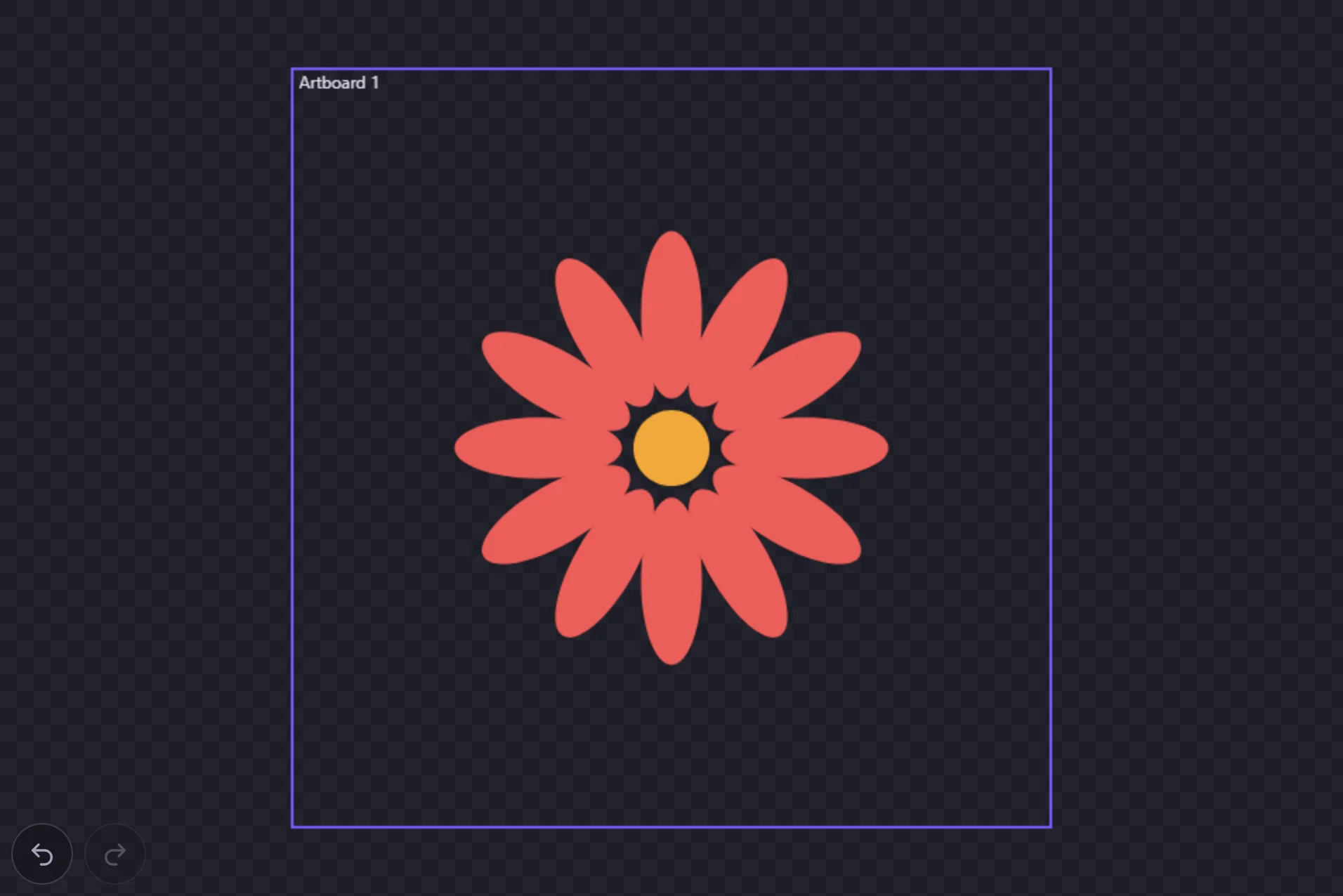
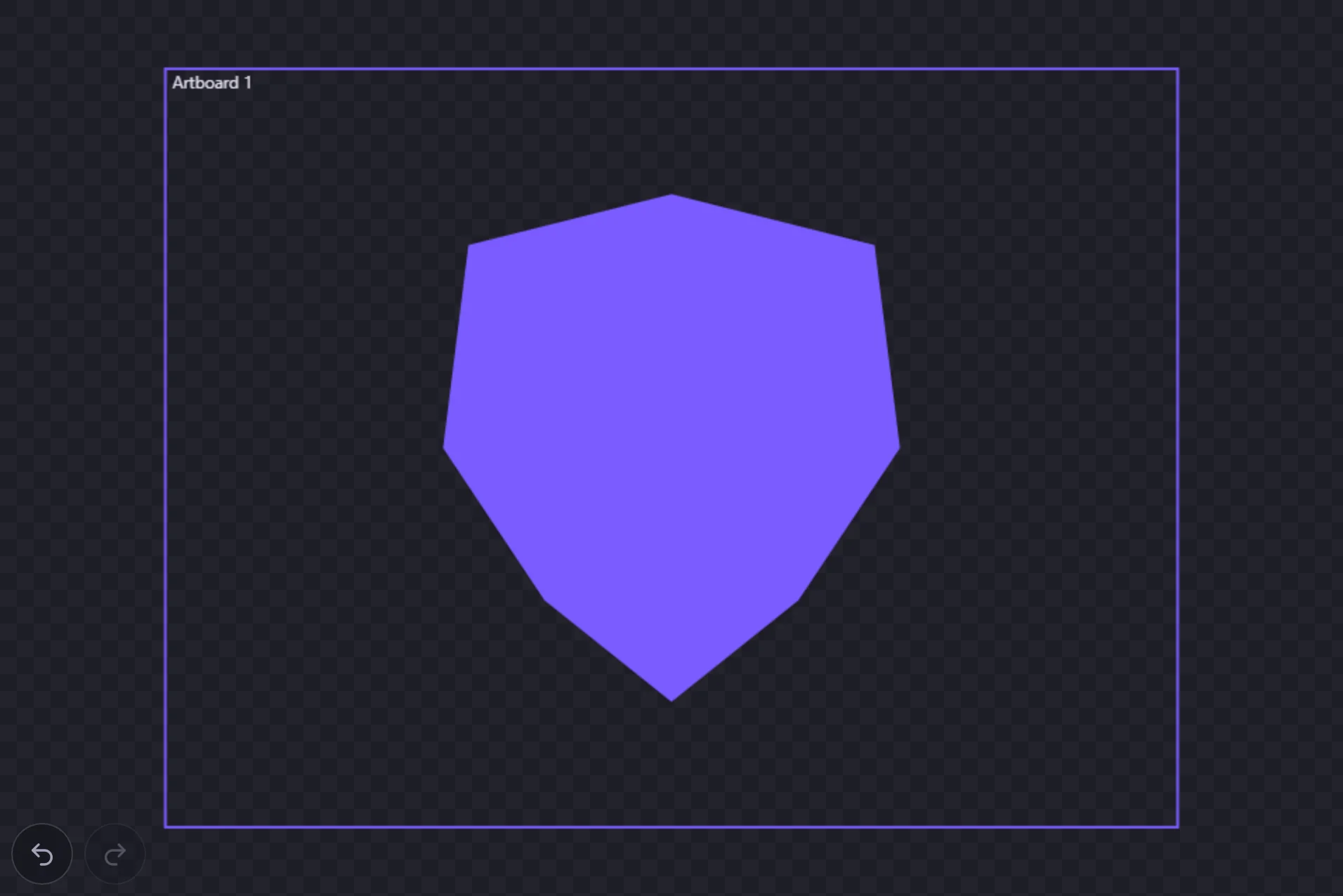
Select one or more shapes and find Repeat in the Inspector, or run Repeat as Grid, Repeat Radially or Repeat as Mirror from the command palette. Choose a mode, set its numbers, and press Make copies. The copies are grouped with the original and the whole thing is one undo step. They are ordinary shapes: editing the original later does not change them.
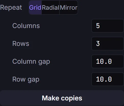
- Grid fills Columns × Rows places (the original takes the first), spaced by Column gap and Row gap. Rows run down the page.
- Radial sets Count copies around a circle, counter-clockwise, spread over the Sweep angle (360° for a full ring). The Centre is the middle of your selection, or a Point you type in as X and Y.
- Mirror flips one copy across a Vertical or Horizontalline placed at the selection's edge or centre. Draw half a symmetrical part and mirror it to finish it.
Repeat works on shapes on one layer. Text, images and dimensions are refused, so convert text to outlines first. One repeat can add up to 2,000 shapes.
Divide overlapping shapes Pro
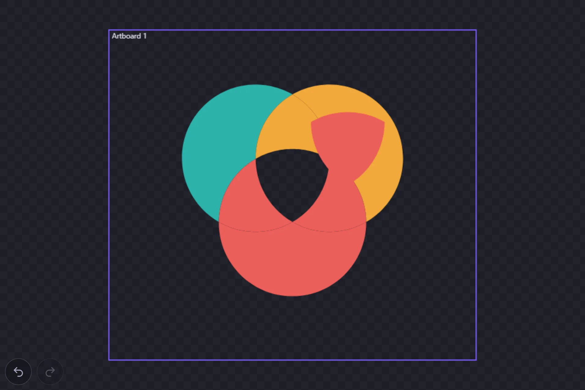
Divide is a Pro feature. Select two or more overlapping shapes on the same layer and press Divide in the Inspector's Combine row, or run Divide Overlapping Shapesfrom the command palette. Every region where the shapes cross becomes its own closed shape, painted with the color of the shape on top there, with any holes kept. Each piece can then be moved, recolored or cut separately. Shapes that don't overlap are left alone, with a note saying there was nothing to divide.
Convert text to outlines
Select a text object and press Convert to outlines in the Inspector, or run Convert Text to Outlines from the command palette. The letters become ordinary vector shapes that a laser, plotter or vinyl cutter follows exactly, and that Repeat and Divide can work on. See converting text to outlines for cut files for the details.
Bevel, emboss & shadows
Raised and pressed edges
Select a shape and open Effects in the Inspector. Enable Bevel, then use its mode row: Bevel gives a raised highlight, and Emboss gives a sharper pressed-light effect. The Width field controls the depth of the edge.
The light falls only on the edge itself, so your fill colors and gradients stay exactly as you painted them — the flat interior of a shape is never tinted.
Drop and inner shadows
Add Drop Shadow for a cast shadow behind the artwork, or switch its Mode to Inner Shadow for a shadow clipped inside the surface. Angle aims the shadow, Distance offsets it, Blur softens it, and Color sets the tint and opacity. There is no separate Glow row in this build; set a Drop Shadow's distance to 0 when you need a soft outside glow.
Choosing what gets bevelled
Applies to picks the surface. Shape bevels the whole shape, fill and stroke together, and is the default. Fill bevels the fill only, leaving the stroke flat. Stroke bevels the stroke on its own — and because a stroke has two boundaries, both its outer and inner edges catch the light.
Lighting
Drag the angle dial to aim the light in document space: 0 points right, 90 points up, 180 points left, and 270 points down. Hold Shift while dragging to snap the angle to the nearest 15 degrees. The dial also takes the keyboard: focus it and use the arrow keys — one degree per press, or hold Shift to snap to that same 15-degree grid. The Light swatch sets the color used by the bevel.
What raster effects cost
SVG export keeps effects as live SVG filter primitives, not a baked bitmap. PNG export rasterises the SVG at the DPI you choose, so higher DPI gives soft shadows and bevels more pixels to resolve into. The tradeoff is that paths are resolved by vector math at any zoom, while a filter result is pixels once rendered. Use effects for editable lighting and soft edges; draw the highlight, shadow, or offset shape as real geometry when that part must be edited as anchors or treated as exact path data.
Constraints & dimensions
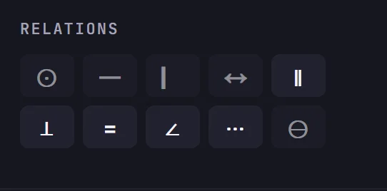
Select points or line segments and add a geometric constraint with the Constraints tool (K) or its right-click menu. Nine kinds are available: coincident, horizontal, vertical, parallel, perpendicular, fixed-distance, equal-length, angle, and collinear. Which are offered depends on the selection: two or more points allow coincident and distance constraints; two or more lines allow parallel, perpendicular, equal-length, angle, and collinear.
The solver applies the constraint to the whole sketch and only commits if it can be satisfied, rejecting a selection that can't form the constraint or one that would over-constrain the sketch. The Constraints panel lists the constraints touching your selection; dimensions (angle, distance) get an editable value and an Adjust option that chooses which geometry the solver is allowed to move. Strict circles and arcs also carry a radius / diameter dimension that drives their size; see Strict vs free curves.
Driving dimensions
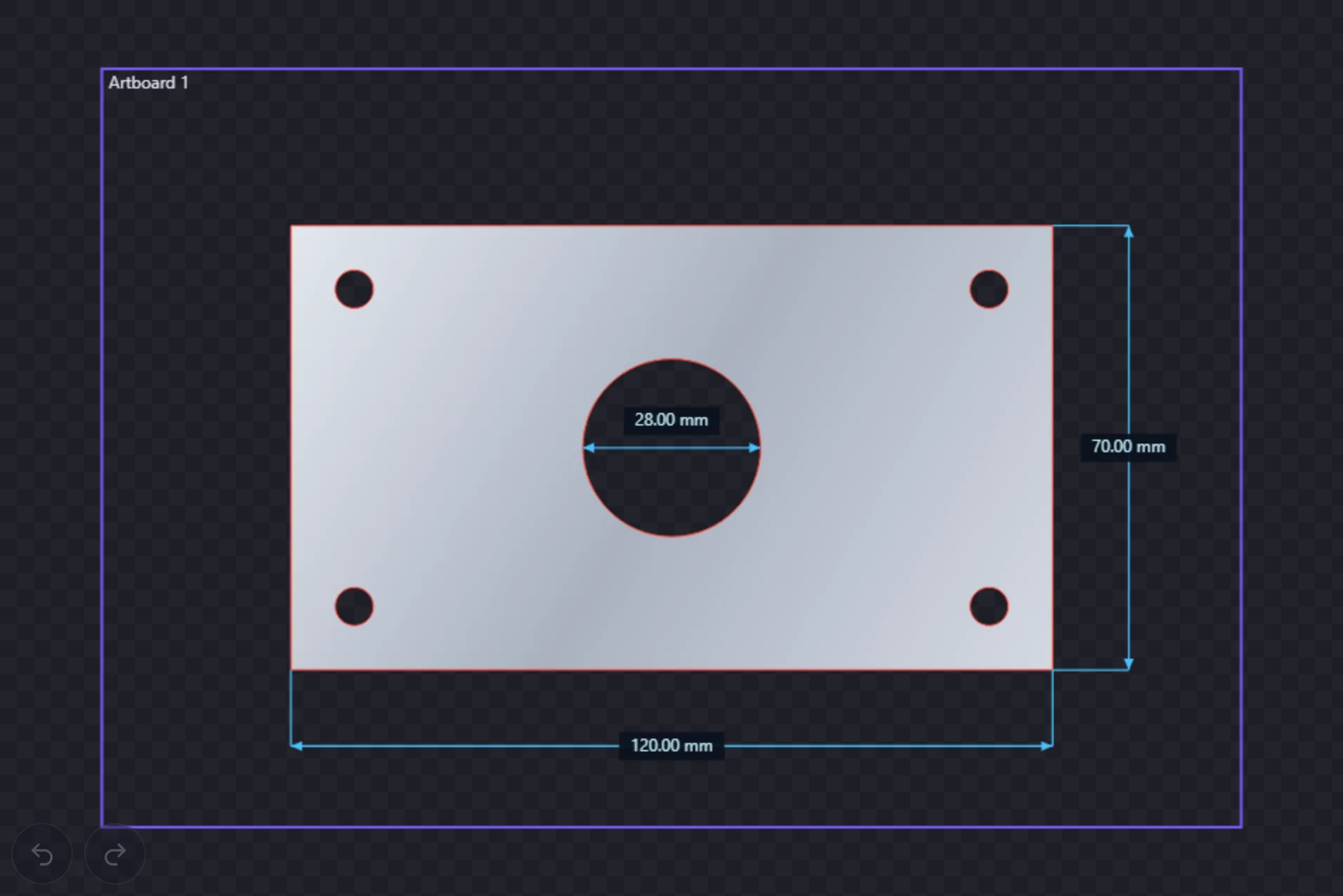
A dimension isn't just a label; it drives the geometry. Place one with the Dimension tool (U) and its type is inferred from what you pick: a line's length, a point-to-point distance, an angle between two lines, a circle's radius, or a perpendicular distance. Edit its value in the Constraints panel and the sketch solves to the new value, resizing the geometry. That is the parametric CAD workflow: set exact numbers, get exact drawings.
- The Adjust picker chooses what the solver moves to satisfy the value: Far end, Both, or Whole shape.
- Chain horizontal and vertical constraints across several points to keep a run of anchors aligned.
- Values read in the document unit, and you can type another inline: enter 25mm while the document is in centimetres and it converts.
Midpoint detection
As you place a dimension with the Dimension tool (U), it snaps to the middle of existing geometry, not just its ends. A straight segment reports Segment midpoint and a curve reports Curve midpoint; the snap label is your confirmation that the dimension references the midpoint rather than a nearby anchor.
Constraints can build from a midpoint too. Snap to a segment or curve midpoint as a point reference and the relation anchors there — the constraint kind is still one of the ordinary relations offered for the selection, just measured from the middle.
Importing artwork
SVG → editable paths
Drop an SVG onto the canvas (or import it from the toolbar) and it becomes editable native paths, not a flat image, scaled to fit and centred in the active artboard, with gradients and fill-rule preserved. Paths, rectangles, circles, ellipses, lines, polylines, polygons, nested groups, and linear/radial gradients are supported; unsupported paint servers (filters, masks) flatten to a solid color.
Raster images
Other image files (PNG, JPEG, WebP) are embedded as picture elements, scaled to fit and centred. They stay export-safe because the pixels are embedded rather than linked.
Trace an image to vector
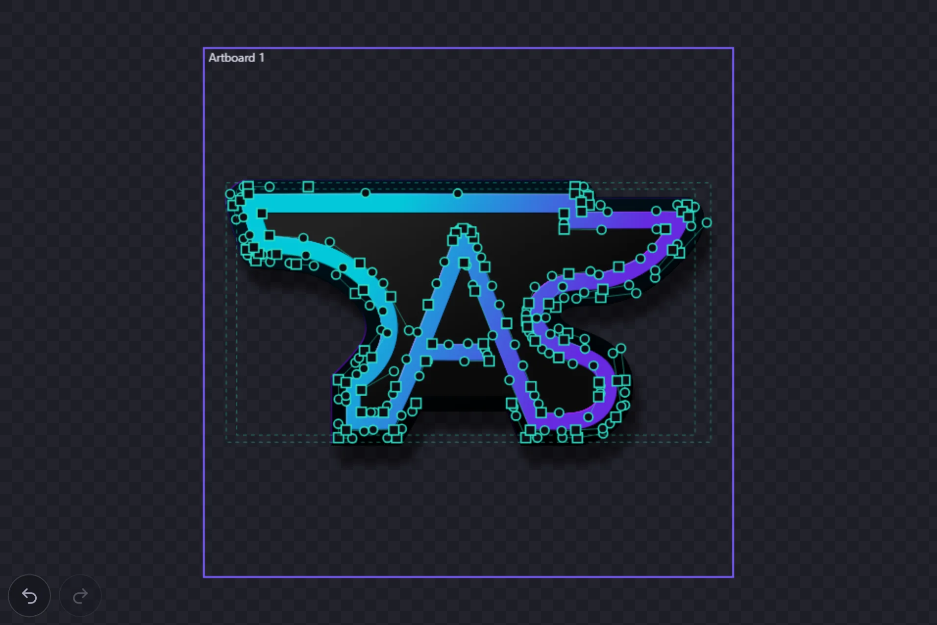
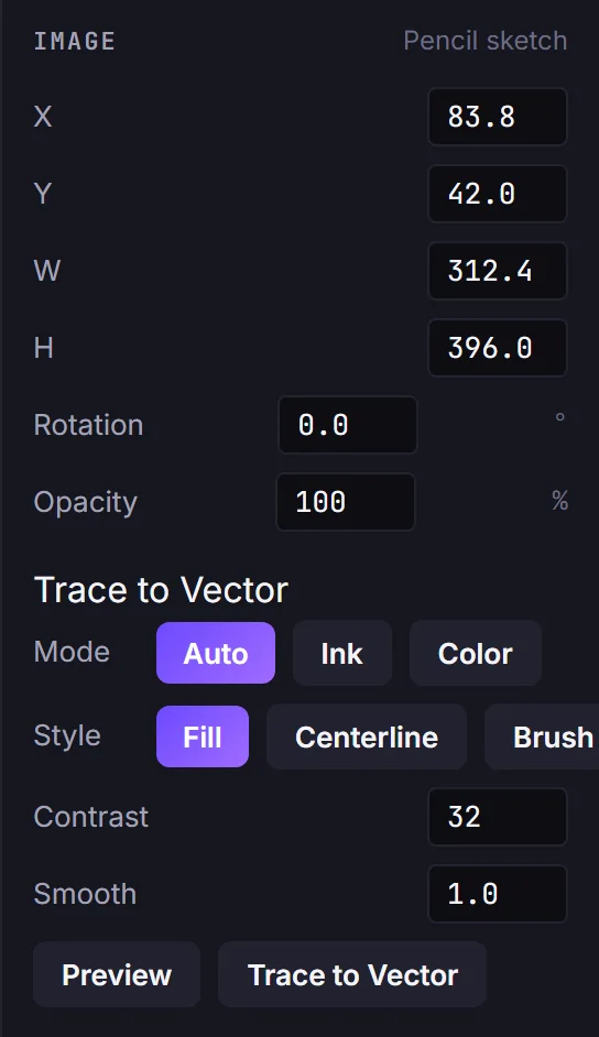
Select a placed image and open the trace control to convert it to vector paths. Choose a mask mode: Auto (polarity-aware, the default), Ink (bright, opaque marks), or Color (flood-fill from points you click); and a style: Fill (filled regions), Centerline (single-stroke skeleton), or Brush (variable-width strokes). Adjust smoothness to trade detail for fewer anchors. Toggle Preview to see the result as animated marching ants, recomputed on a downscaled image so it stays responsive, before committing.
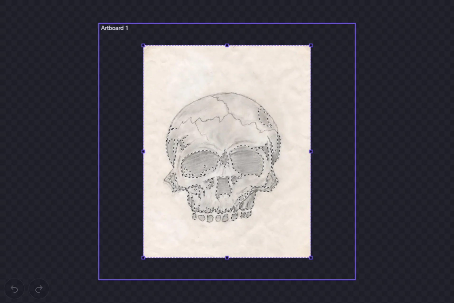
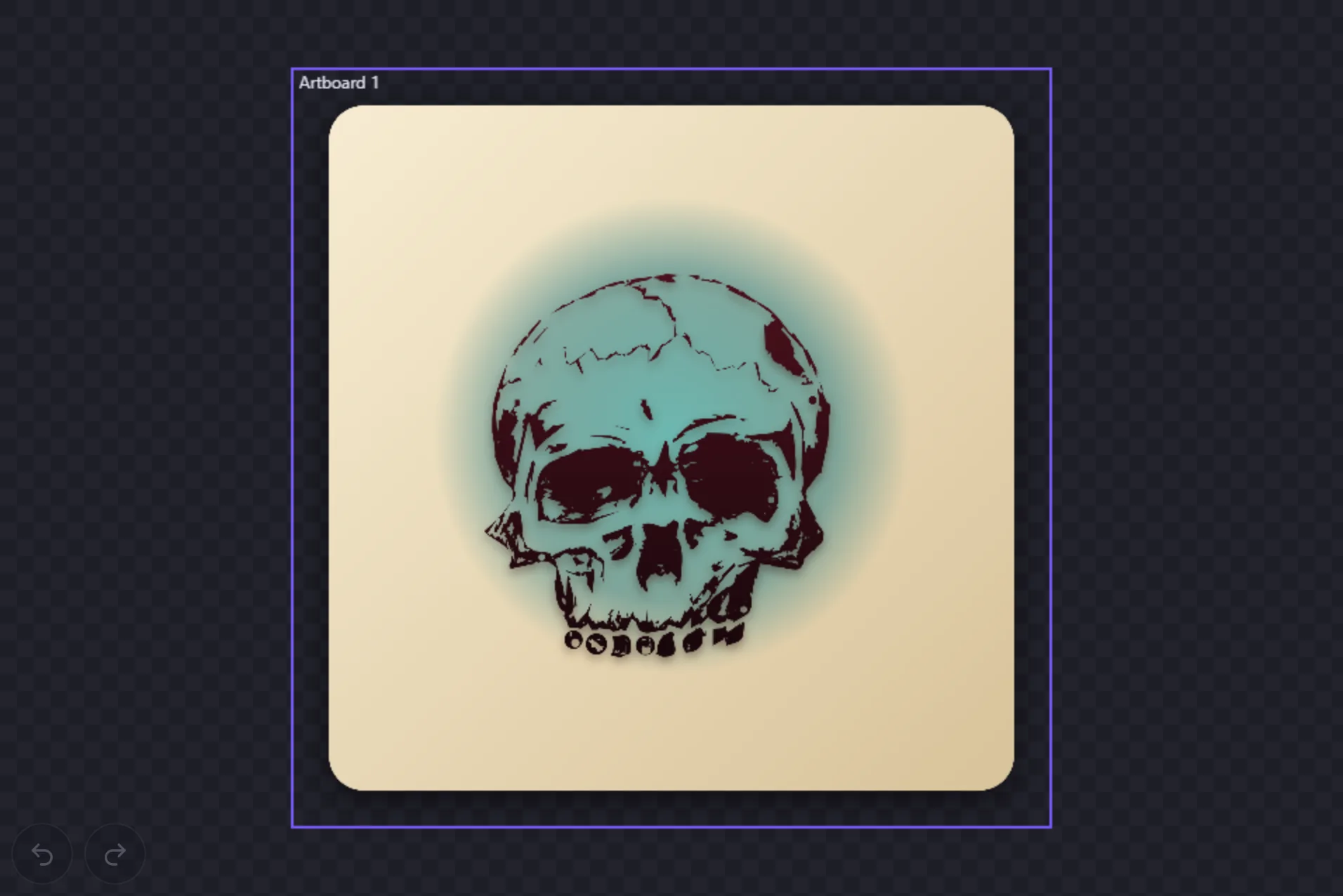
A trace is a starting point, not the finish. What it gives you is ordinary editable paths, so everything else in the editor applies: gradient fills, shadows, new colors, a backdrop.
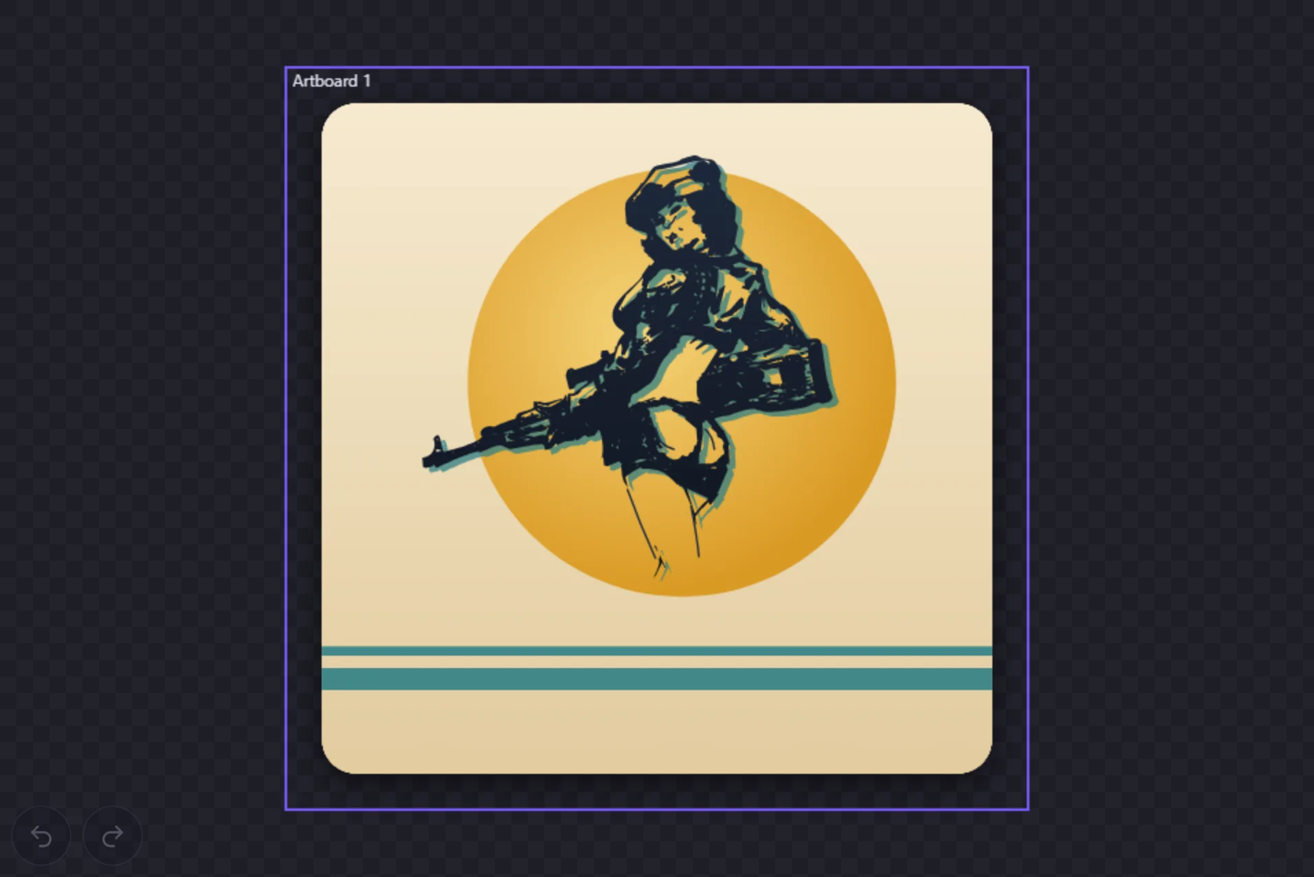
For a full worked example, with the real settings, a first attempt that did not work, and what was refined by hand, see how the pin-up was made.
Workflows
A few end-to-end paths through the tools above.
1 · Trace an image to vector
- Drag a raster image onto the canvas (or import it), then select it with the Selection tool (V).
- In the Image section of the side panel, choose a trace Mode (start with Auto) and a Style (Fill, Centerline, or Brush).
- Toggle Preview to see the live marching-ants result, and adjust Smooth until it looks right.
- Click Trace to Vector, and the image is replaced by an editable vector shape, selected for you.
- Style it: it is an ordinary path now, so give it a gradient fill, a shadow, a backdrop.
2 · Draw, constrain, and dimension
- Draw two lines with the Line tool (L).
- Switch to Selection (V) and select both lines.
- With the Constraints tool (K), press a key to add a relation, e.g. P for parallel or O for perpendicular.
- With the Dimension tool (U), click a line then empty space to place a driving length; edit its value to resize.
3 · Pick a color with the eyedropper
- Select a shape and open its Fill or Stroke swatch to bring up the color picker.
- Click the pipette. On Chrome/Edge, click anywhere on screen; on Firefox/Safari the cursor becomes a crosshair, so click your canvas to sample.
- On Firefox/Safari, use “Pick from another app” to sample from a shared screen frame instead.
4 · Drag-import an SVG
- Drag an .svg file from your desktop onto the canvas.
- It imports as editable native paths, scaled to fit and centred, with gradients and fill-rule preserved.
- Switch to Direct Selection (A) to edit its anchors, or recolor it from the Inspector.
Layers & artboards
Layers
The Layers panel is a tree of layers, groups, and elements. Toggle visibility and lock, rename in place (double-click), reorder, search by name, and delete (a document always keeps at least one layer). Each row carries a thumbnail so you can find artwork fast.
Artboards
Add, duplicate, rename, and delete artboards; each defines an export region. New artboards are placed beside the active one, and export resolves bounds from the active (or a chosen) artboard.
Clipping masks
Make a clipping mask
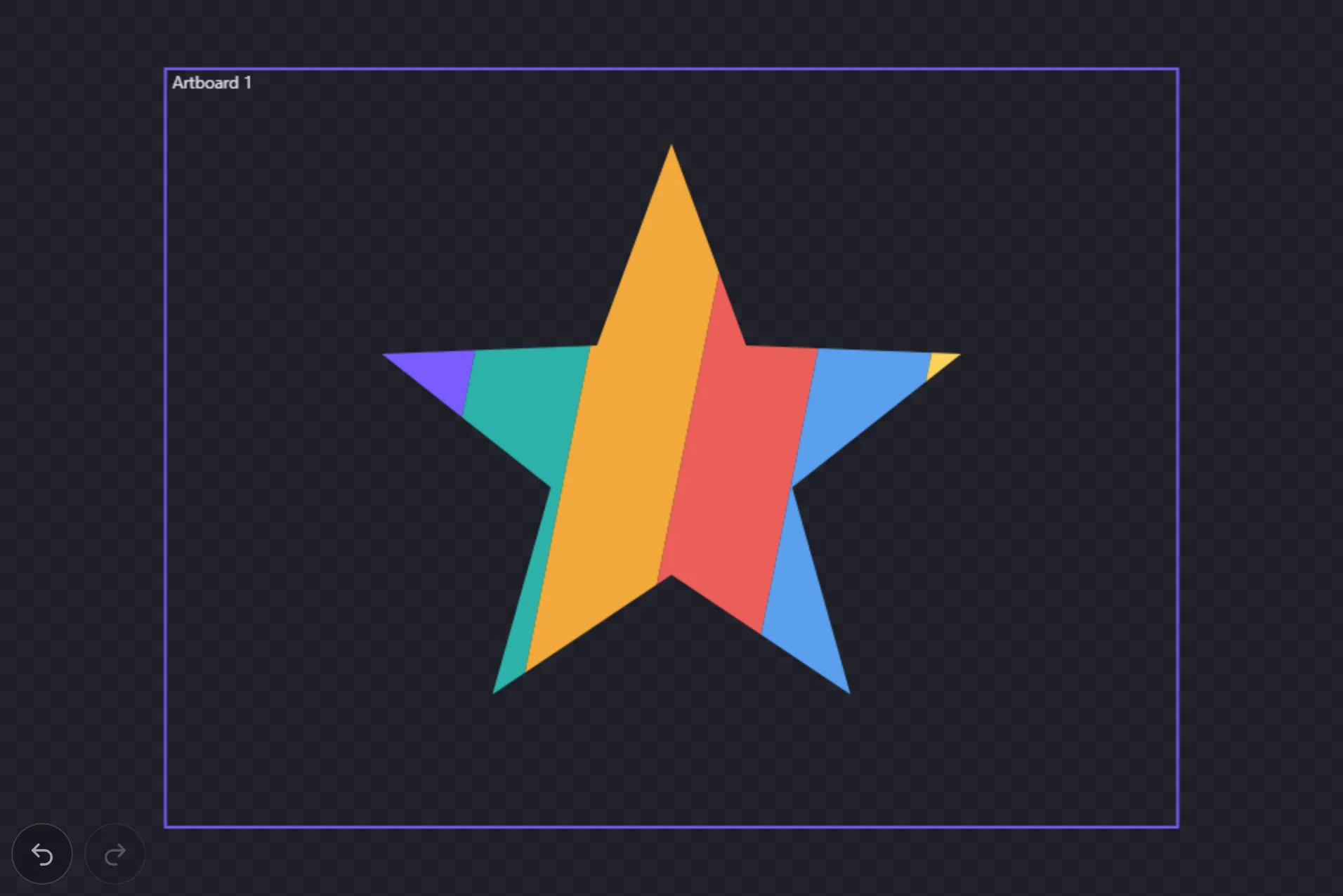
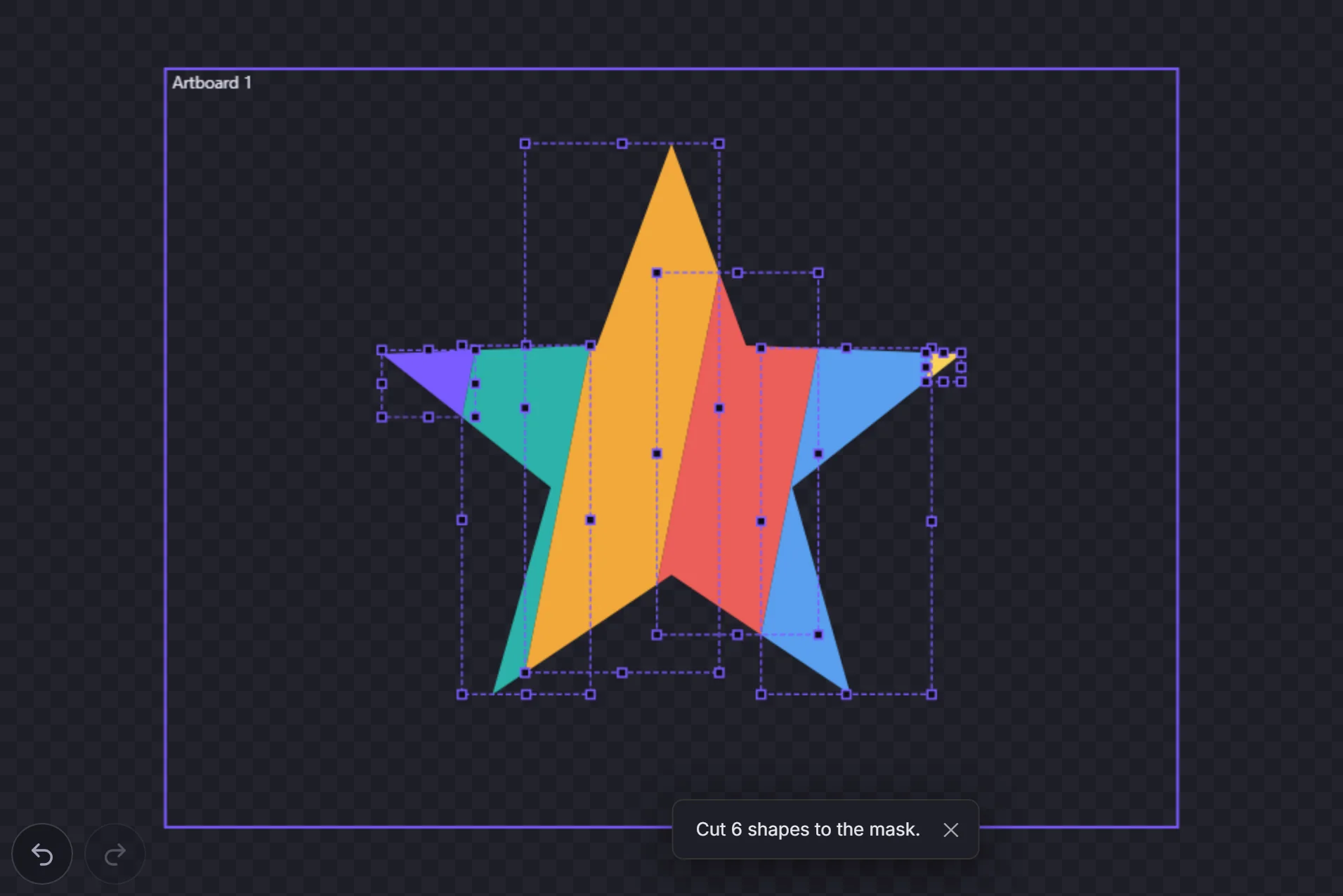
Select the artwork and, on top of it, the shape you want to see it through, all on one layer. Press Ctrl+7, right-click and choose Make Clipping Mask, or run it from the command palette. The topmost selected shape becomes the clipping path: the rest of the selection now shows only inside it, and the clipping path itself is not painted. Nothing is cut or deleted, so the artwork and the path both stay editable. Text and images in the mask are clipped too.
Find it in the Layers panel
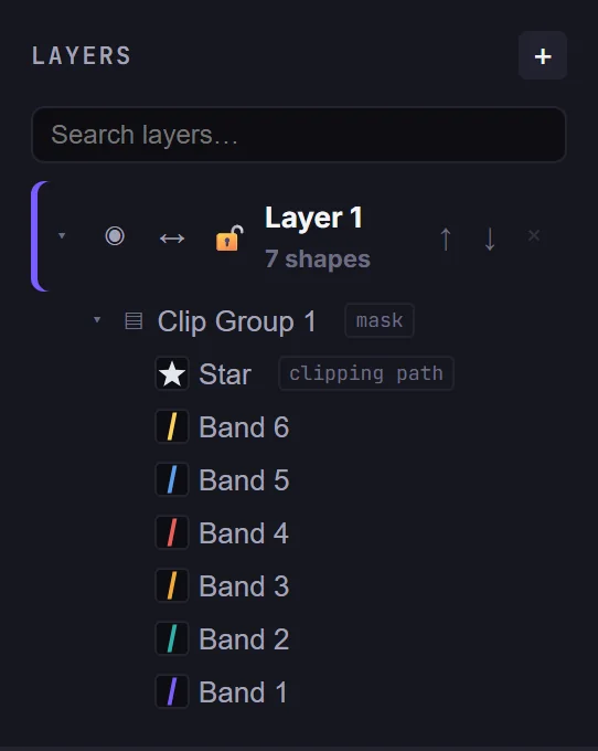
A clipping mask is a group. In the Layers panel its row is tagged mask, and the shape doing the clipping is tagged clipping path. Select the group to see the clipping path's outline on the canvas. Masks can sit inside masks: content shows only where every mask around it allows.
Release a mask
Select the mask, or anything in it, and press Ctrl+Alt+7 or choose Release Clipping Mask. The group stays, and the clipping path comes back exactly as it was drawn, fill and stroke included.
Clipping masks and cut files
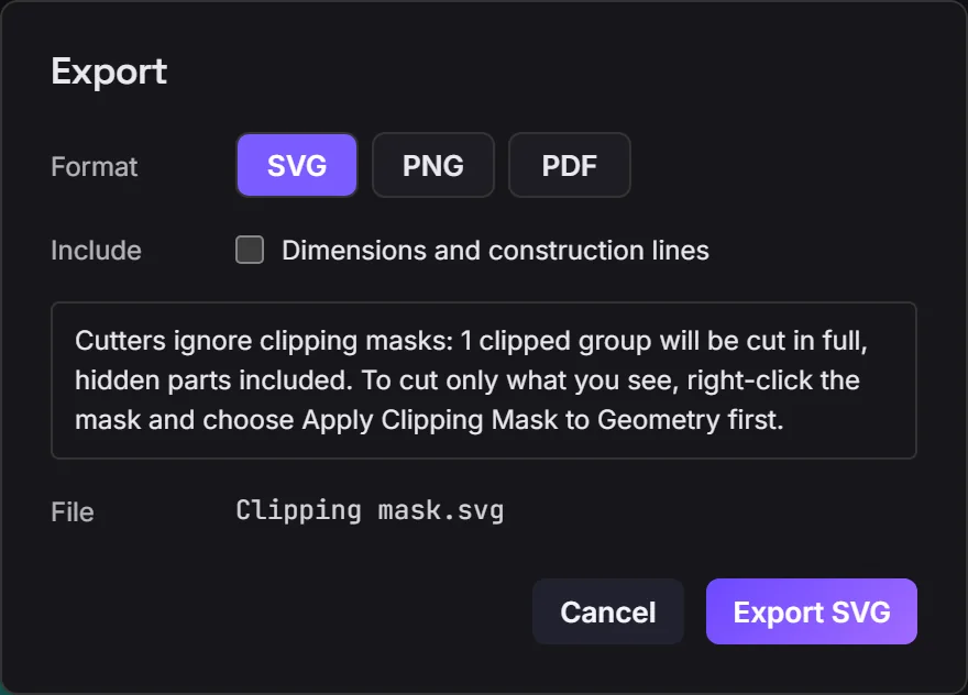
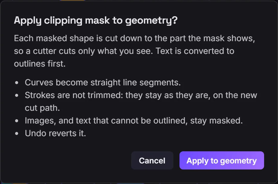
Lasers, plotters and vinyl cutters ignore clipping masks: they cut every path in full, including the parts a mask hides. The Export dialog warns you when a document has a mask. To cut only what you see, right-click the mask and choose Apply Clipping Mask to Geometry. After a confirmation, each shape is cut down to the part the mask shows, text is converted to outlines first, and the clipping path is removed. Before you confirm, know what changes:
- Curves become straight line segments.
- Strokes are not trimmed: they stay as they are, on the new cut edge.
- Images, and text that cannot be converted to outlines, stay masked, and the mask stays for them.
One undo brings the mask back.
Exporting
Export the active artboard as SVG, PNG, or PDF. SVG is the source of truth: standards-valid, with the web fonts you used embedded so it renders in-brand anywhere. Shape geometry and Anchorsmith effects stay in SVG as vector paths plus live filter primitives. PNG rasterises that SVG at the DPI you choose: the menu derives its DPI labels from the document setup while the exporter scales the raster to 1×, 2×, or 4×. PDF is true vector, page-sized to the artboard in points.
History & saving
Undo and redo cover the last 256 steps (Ctrl+Z / Ctrl+Shift+Z), and the same two actions sit on the canvas itself, bottom-left. On a touch device those buttons are the only route — there is no Ctrl key to press. They stay on screen but dimmed when there is nothing to undo, and on a desktop hovering one names the exact edit it will reverse. A continuous gesture such as a drag folds into a single step.
Signed-in documents also support manual checkpoints: save a restore point, and restoring it keeps your current progress as an undo step, so it's never destructive.
Automating with an AI Agent (SDK Preview)
The editor exposes a programmatic action API so an AI agent can build and edit documents directly. You call executeAgentAction with a document, a commit wrapper, and a command; you observe the document with getAgentDocumentSnapshot and the other perception helpers. All geometry is in Y-up document space.
executeAgentAction({
  doc, commit,
  command: { kind: "createRect", id: "box", x: 100, y: 100, width: 200, height: 120 },
});
executeAgentAction({
  doc, commit,
  command: {
    kind: "setFill",
    ids: ["box"],
    fill: { enabled: true, color: { r: 240, g: 80, b: 60, a: 1 }, paint: { kind: "solid" } },
  },
});const snap = getAgentDocumentSnapshot(doc);
// snap.summary.shapeIds -> ["box", ...]
// snap.svg -> rendered SVG string
// snap.json -> full serialized documentThe full machine-readable spec (every command, its parameters, the perception API, and the coordinate contract) is served as plain text for an agent to fetch and parse: